Mold Structure and Process Knowledge: Key Points from Design to Assembly
October 05, 2026
When we talk about mold structure, the first thing to lock down is the parting line and cavity layout. In a typical two-plate mold for an injection-molded ABS part, shrinkage runs about 0.4–0.7%, so cavity dimensions must be scaled accordingly before any steel is cut. The gating system matters just as much: a side gate of 0.8–1.2 mm depth works well for small parts, while a hot runner system makes sense once annual volume exceeds roughly 100,000 shots. Cooling layout should follow the part geometry—baffles and bubblers in deep cores, and a uniform 12–15 mm center distance between cooling lines to avoid hot spots and warpage.
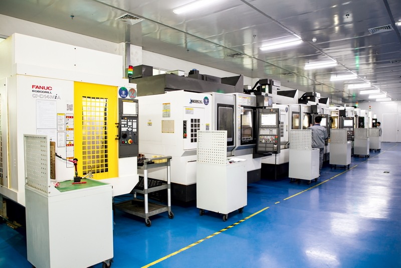
On the manufacturing side, mold base plates are usually made from S50C or P20, while cores and cavities for abrasive resins like glass-filled PA66 call for hardened steel such as SKD61 or H13, heat-treated to 48–52 HRC. CNC roughing removes the bulk, EDM handles sharp internal corners and deep ribs, and wire EDM cuts the parting line inserts with tolerances held to ±0.01 mm. Polishing follows a stepwise grit sequence—from #400 up to #1200 or diamond paste for optical surfaces. Fitting the ejector plate, guide pins, and return springs during assembly is where many shops lose time, so pre-assembly checks on plate parallelism (within 0.02 mm) save rework later.
Assembly is not just bolting plates together. You need to verify shut-off surfaces, check slide and lifter travel, and confirm the ejector system strokes cleanly without binding. A dry run before T1 sampling catches most interference issues. For anyone sourcing molds or comparing suppliers, visiting MoldWorld (www.moldw.com) gives access to mold sourcing information and supplier listings that can shorten the vetting process.