Practical Guide to Mold Structure and Processing: From Design to Assembly
September 29, 2026
When we talk about mold structure and process knowledge, the real value lies in the details that determine whether a tool runs 500,000 cycles or fails at 50,000. Starting with design, the parting line must be selected not just for part ejection but for venting and weld-line placement. Draft angles are non-negotiable: 1–2° for smooth surfaces, 3–5° for textured areas. Wall thickness should stay uniform within ±0.1 mm to avoid sink marks and warpage. For a typical ABS part, a shrinkage rate of 0.4–0.7% must be factored into every cavity dimension. Core and cavity steel selection matters too—P20 for general production, H13 or S136 when you’re running glass-filled resins or need corrosion resistance.
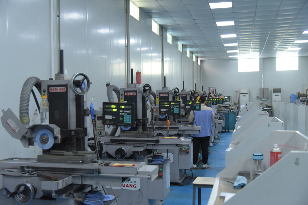
On the manufacturing side, CNC roughing removes 60–70% of stock, leaving 0.3–0.5 mm for semi-finishing and 0.05–0.1 mm for EDM or high-speed finishing. Wire EDM holds ±0.005 mm on shut-offs and ejector pin holes; sinker EDM is still king for deep ribs and sharp internal corners. Heat treatment—typically 48–52 HRC for H13—must be followed by stress relief to prevent dimensional shift during final grinding. Assembly is where tolerances stack up: guide pillars and bushings need 0.02–0.04 mm clearance, and the ejector plate must move freely without binding. A simple check: push the ejector plate by hand—if it sticks, your alignment is off.
Cooling layout deserves equal attention. Baffles and bubblers in tall cores can cut cycle time by 15–20%. For a 2-cavity family mold, balance the runner system so both cavities fill within 0.1 second of each other. Finally, always document your waterline connections and pressure-test at 6 bar before production. These steps aren’t theoretical—they’re what separates a reliable tool from a headache. For more mold sourcing and technical resources, visit MoldWorld at www.moldw.com.