Plastic Mold Fundamentals: How the Moving Half and Fixed Half Divide the Work
August 26, 2026
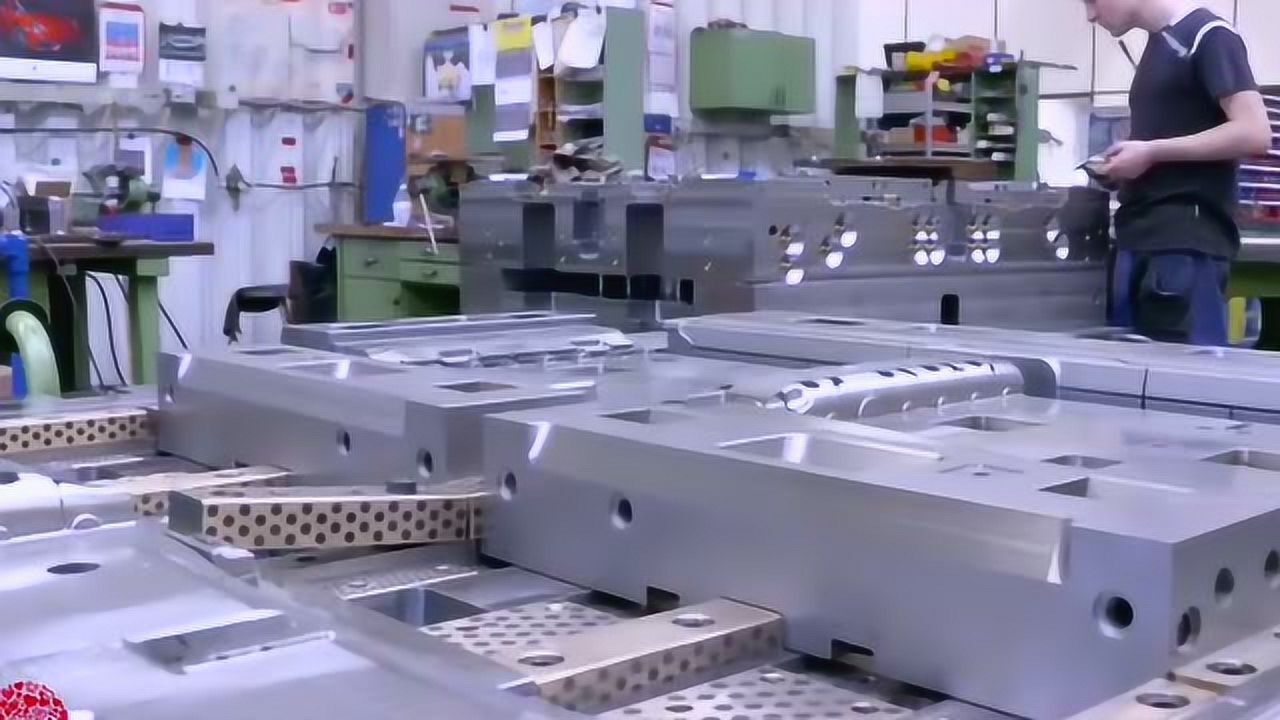
In any standard two-plate injection mold, the division of labor between the moving half (动模) and the fixed half (定模) is not arbitrary—it follows the physics of melt flow and part ejection. The fixed half, mounted on the injection unit side, houses the sprue bushing, locating ring, and often the runner system. Its primary job is to deliver molten resin from the machine nozzle into the cavity. Because this half sees the highest melt pressure and temperature, it typically uses hardened tool steel (e.g., P20 or H13) for the cavity inserts, with cooling channels designed to remove heat from the gate area first. In contrast, the moving half carries the ejection mechanism—ejector pins, return pins, and sometimes lifters or slides—because the part must stay on this half after the mold opens. This is achieved by placing a slight draft angle (0.5° to 1.5° per side) on the core side, which grips the part as the mold splits. The moving half also contains the main support pillars and the ejector housing, which must be rigid enough to withstand repeated cycling without deflection.
The real engineering nuance lies in how the two halves interact during clamping and opening. During injection, the clamping force (typically 3–5 tons per square inch of projected area) presses the parting line tight, preventing flash. But after cooling, the mold opens at the parting line, and the moving half pulls away, carrying the part on the core. The ejection stroke—usually 20–50 mm depending on part depth—then pushes the part off. A common mistake in mold design is placing deep ribs or bosses on the fixed half side, which forces the part to stick to the nozzle side and complicates ejection. Experienced mold engineers always orient the part so that the largest surface area and all undercuts are on the moving half, allowing simple straight-pull ejection. For undercuts, slides or lifters are mounted on the moving half, while the fixed half only handles the sprue puller—a small Z-shaped or reverse-taper pin that yanks the solidified sprue out of the sprue bushing during opening.
Temperature control further differentiates the two halves. The fixed half, being closer to the nozzle, runs hotter—often 10–20°C above the moving half—to keep the gate area flowing. The moving half, where the part cools and shrinks, uses more aggressive cooling lines, sometimes with baffles or spiral cores for deep cavities. In production, this imbalance means the mold designer must calculate cooling channel placement separately for each half, using flow rates of 1–2 gallons per minute per circuit. If the moving half runs too hot, the part will stick to the core; if too cold, sink marks appear near the gate. A well-balanced mold keeps the temperature differential within 5°C across the parting line. For mold buyers or maintenance teams, understanding this split logic helps diagnose issues like short shots (fixed half flow restriction) or ejection marks (moving half drag). For a deeper look at mold construction details, sourcing guides, and supplier comparisons, visit MoldWorld at www.moldw.com—a practical resource for mold engineers and procurement specialists.