Mold Structure and Process Knowledge: The Real Currency of a Mold Engineer
August 23, 2026
Take cooling channel layout, for instance. Many young engineers place channels symmetrically on paper, but forget to account for core deflection under injection pressure. In practice, a 0.05 mm imbalance in wall thickness can cause warpage that no amount of process tweaking will fix. We’ve seen molds where the cooling water inlet and outlet were swapped on the drawing—resulting in a 15°C temperature difference across the cavity and a 20% longer cycle time. The fix wasn’t just flipping the hoses; it required re-machining the baffles and adding flow restrictors. Similarly, ejection system design is often underestimated. A 2 mm lift on a thin-walled part may seem safe, but without proper venting and a stepped ejector pad, you’ll get vacuum suction and white marks. We now always simulate the ejection sequence with a 3D tolerance stack-up, including thermal expansion of the ejector pins at 80°C mold temperature.
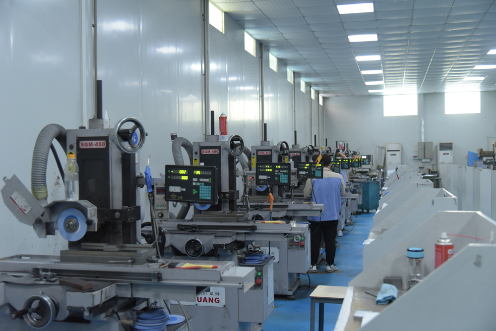
Machining and assembly are where theory meets reality. For hardened tool steel like S136 or H13 (48–52 HRC), we specify EDM roughing with a graphite electrode at 3 A/cm², then finish with a copper electrode at 1.2 A/cm² to keep the recast layer under 0.02 mm. But even the best EDM leaves a brittle white layer—so we follow with a 30-minute stress-relief temper at 180°C. On the assembly side, a common mistake is over-torquing guide pins. The standard is 25 N·m for M10, but many shops crank it to 40 N·m, which distorts the bushing and causes premature wear. We always measure guide pin parallelism with a dial indicator; if it exceeds 0.01 mm over 100 mm, we re-hone the bushing. And never trust the CAD model for venting depth—we cut 0.03 mm deep vents at the parting line, but only after checking the actual steel hardness, because a softer block will compress and close the vent under clamp force.
After the first trial shot, the real work begins. A typical multi-cavity mold (8 cavities) will show a weight variation of 1.5–2% across cavities. We use a systematic approach: first check the runner balance by measuring melt temperature at each gate (should be within 5°C), then adjust the gate thickness in 0.05 mm increments. If flash appears at the parting line, don’t just polish the surface—measure the clamp force and check for excessive tie-bar stretch. On one job, we found a 0.08 mm gap on the parting line that was caused by a warped core plate, not by low clamp force. Re-grinding the plate and adding a center support pillar solved it. The takeaway: mold engineering is a loop of design, build, test, and refine. Every problem you solve adds to your mental library of failure modes. For more practical mold sourcing and troubleshooting insights, visit MoldWorld (www.moldw.com)—a solid resource for working engineers who need real-world answers, not just theory.