Plastic Mold Dynamic/Fixed Half Alignment and Overmolding Process Essentials
August 22, 2026
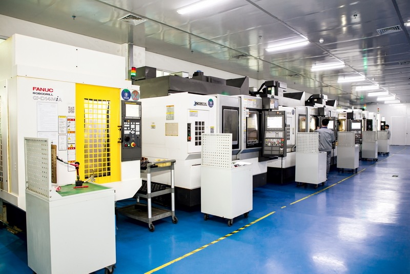
In plastic injection mold construction, the alignment between the dynamic half (moving side) and the fixed half is the single most important factor affecting part consistency and tool longevity. For standard molds, we typically specify a guide pillar and bushing clearance of 0.02–0.03 mm on the fit diameter, with a surface hardness of HRC 58–62 after nitriding. However, for high-cavitation molds or those running engineering resins like PC/ABS or PBT+30%GF, we recommend zero-clearance taper locks (e.g., 5°–7° included angle) in addition to the conventional guides. This prevents lateral shift during high-pressure packing, which can exceed 800 bar in the cavity. A common field issue is "flash on the parting line" caused by uneven clamping force distribution—often traced to insufficient support pillars behind the support plate. Always add at least four support pillars (Ø25 mm or larger) positioned directly under the cavity blocks, and verify the plate deflection with a dial indicator during tryout; keep it under 0.02 mm at 80% of max clamp tonnage.
For overmolding (two-shot or insert molding), the dynamic/fixed half relationship becomes even more critical because the first-shot substrate must be precisely located in the second cavity. The key is to design a steel-to-steel shut-off around the substrate’s edge, with a minimum overlap of 1.5 mm and a clearance of 0.01–0.02 mm. This prevents flash from bleeding onto the first-shot surface. In practice, we often add a spring-loaded locator in the moving half to hold the substrate against the fixed half’s core, compensating for any shrinkage variation (typically 0.3%–0.6% for ABS, 0.5%–0.8% for nylon). For TPE overmolding onto rigid plastic, the melt temperature must be controlled within a narrow window—usually 190°C–210°C for SEBS-based TPEs—and the substrate surface should be pre-treated with a corona discharge or primer if adhesion below 1.5 N/mm is observed. Also, remember to add adequate venting (0.02–0.03 mm deep, 6–8 mm wide) at the last fill points, because trapped gas causes voids in the overmold layer.
Another practical point is the mold temperature control strategy for overmolding. Unlike standard injection, the second-shot cavity often needs a higher mold temperature (60°C–80°C) to promote bonding, while the first-shot core can be cooled to 40°C–50°C to reduce cycle time. Use independent temperature control zones for the fixed and moving halves, and consider a hot runner with a shut-off nozzle for the second shot to avoid drooling. During process validation, run a “short-shot” matrix to confirm the substrate is not deformed by the second-shot pressure—especially if the wall thickness is below 1.2 mm. If you see sink marks or warpage, reduce the second-shot injection speed by 20% and increase the holding pressure gradually until the part weight stabilizes. For more detailed mold design guidelines and sourcing of specialized overmold tooling, visit MoldWorld at www.moldw.com—a practical resource for mold engineers looking for verified suppliers and technical data.