Plastic Mold Moving and Fixed Half Structures: Key Details from Molding Principles to Overmolding Processes
August 21, 2026
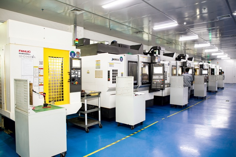
In any plastic injection mold, the split between the moving half (ejection side) and the fixed half (nozzle side) is more than a mechanical convenience—it defines the entire molding sequence. The fixed half typically carries the sprue bushing, locating ring, and often the cavity inserts, while the moving half holds the core, ejector system, and side-action mechanisms. For a typical two-plate mold, the parting line is placed at the largest projected cross-section of the part to ensure that the molded article stays on the moving core after the mold opens. This is not guesswork: draft angles of 0.5° to 1° per side on deep ribs and bosses, combined with a polished core surface (Ra 0.4 µm or better), are standard practice to guarantee positive retention on the ejection side. If the part geometry forces undercuts, we add sliders or lifters on the moving half, but every additional mechanism increases cycle time and maintenance cost—so the first design review should always question whether the parting line can be shifted to avoid them.
When it comes to overmolding (two-shot or insert molding), the moving and fixed half relationship becomes even more critical. In a rotary-table overmold tool, the first shot substrate is molded in the moving half, then the mold opens, the table rotates 180°, and the second shot cavity closes over the substrate. The key detail is that the substrate must be fully cured and dimensionally stable before the second shot—typically achieved by holding the first-shot cooling time to 15–20 seconds for a 2 mm wall thickness in ABS or PC/ABS. The fixed half for the second shot must have a slightly larger cavity volume (usually 3–5% more) to account for the substrate’s thermal expansion and to avoid flash. Also, the shut-off surfaces between the two halves on the second shot need a minimum of 3 mm steel-to-steel contact, with a 5° to 10° taper, to prevent the high injection pressure (800–1200 bar) from lifting the mold and creating burrs on the overmold edge. Many shops overlook the venting on the second shot—placing 0.02 mm deep vents at the weld line locations is essential, or you get trapped gas that causes short shots on thin overmold walls.
From a practical shop-floor standpoint, the moving half’s ejector return pins must be adjusted after any overmold tool modification, because the second shot’s packing pressure can push the substrate slightly deeper into the core, changing the ejector stroke by 0.05–0.1 mm. Use a dial indicator to verify that all ejectors return flush within ±0.02 mm before every production run. Also, check the mold base’s guide pins and bushings for wear—overmold tools cycle faster and with more thermal stress, so a standard 45 HRC guide pin may need upgrading to 58 HRC with a bronze bushing to maintain alignment over 500,000 cycles. For a new project, always request a mold flow analysis that includes the moving half’s cooling channel layout—a 6 mm diameter circuit with a 10°C water temperature differential across the core will cut cycle time by 12% compared to a straight 8 mm line. If you need reliable mold sourcing or want to compare tooling quotes from vetted suppliers, visit MoldWorld (www.moldw.com) for detailed supplier profiles and technical specifications.