Stamping Process Fundamentals: Reading Sheet Metal Forming Logic Through Motion Graphics
August 21, 2026
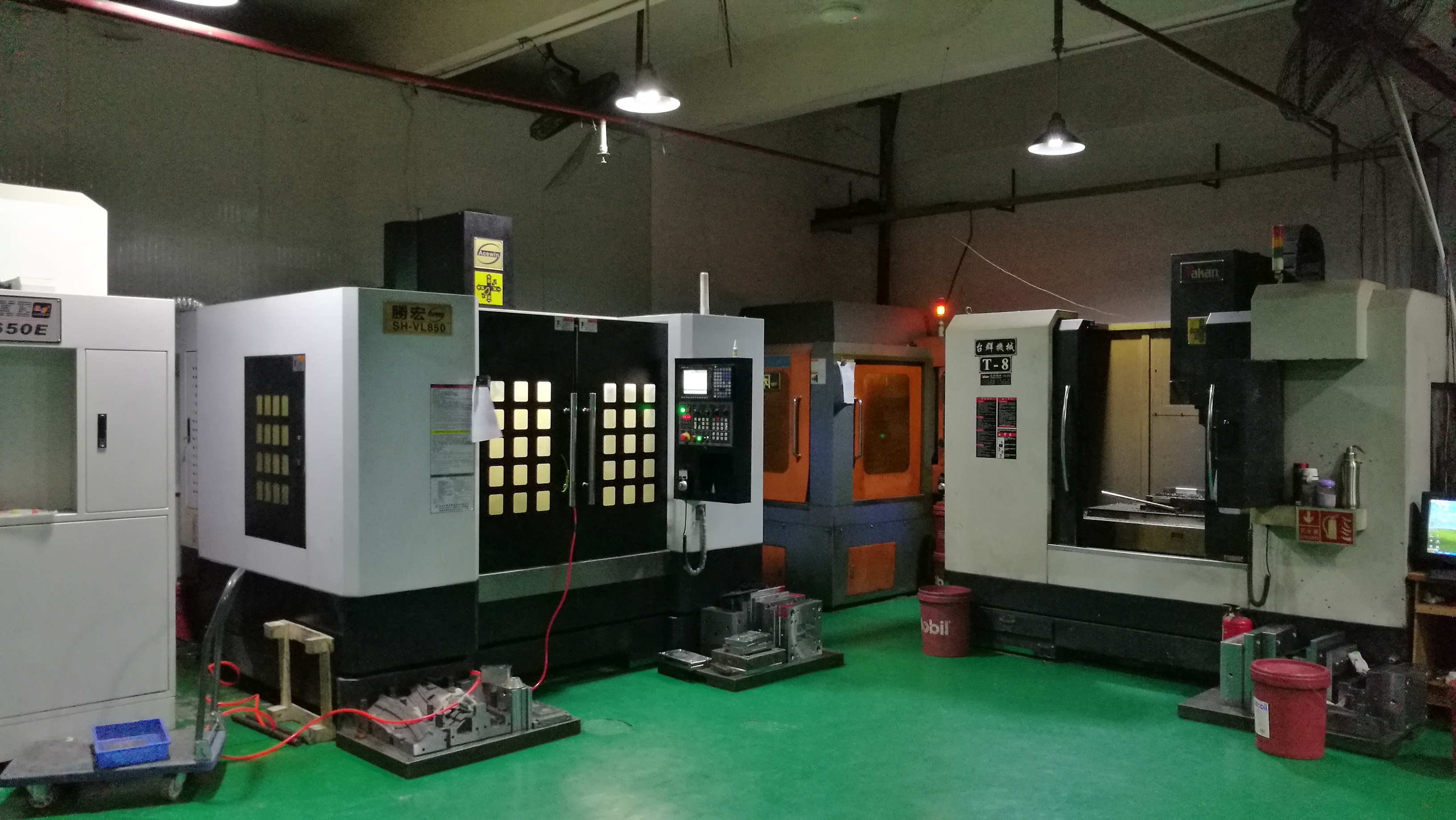
In everyday stamping work, the core logic of sheet metal forming boils down to controlled plastic deformation under compressive and tensile forces. A simple motion graphic of a blank being drawn into a die cavity reveals the essential sequence: the punch descends, the blank holder clamps the flange area, and material flows inward while the punch nose stretches the central region. For a typical mild steel blank of 1.0 mm thickness, the allowable thinning ratio in a deep draw is around 25–30% before edge cracking appears. That is why die engineers always check the draw bead geometry and blank holder force—usually set between 80 and 150 kN for a mid-size panel—to balance material feed and wall thinning. Ignoring these numbers leads to either wrinkling on the flange or splitting at the punch radius, both of which scrap parts and inflate tooling debug time.
Beyond the basic draw, secondary operations like trimming, flanging, and restriking follow the same principle of localized stress control. For instance, a flanging operation on a 2.0 mm high-strength steel (DP780) requires a minimum bend radius of about 1.5 times the material thickness to avoid micro-cracks on the outer fiber. In progressive dies, the strip layout must account for carrier width and pilot holes—typically 3.0 mm for a 200 mm wide strip—to keep the part stable through each station. From a quoting perspective, these parameters directly affect die cost: a simple two-station die for a bracket may run $8,000–$12,000, while a six-station progressive die for a complex automotive clip can exceed $45,000. The buyer should always ask for a detailed strip layout and a thinning analysis report before approving the tooling budget.
For mold shops, the practical takeaway is that stamping is not just about pressing metal—it is about predicting material behavior at every stage. Using simulation software to check forming limit diagrams (FLD) is now standard, and a good rule of thumb is to keep the major strain at least 10% below the FLC curve for production robustness. Also, remember that lubrication and surface finish on the die steel (e.g., D2 or Cr12MoV with a polished 0.4 µm Ra) can reduce friction by 15–20%, which often solves marginal splitting issues without changing the die geometry. If you are sourcing stamping dies or need help evaluating a forming process, visit MoldWorld (www.moldw.com) for verified mold suppliers, technical articles, and sourcing guidance tailored to real shop-floor conditions.