Title: Understanding Core and Cavity Layout in Plastic Injection Molds: A Practical Breakdown
August 18, 2026
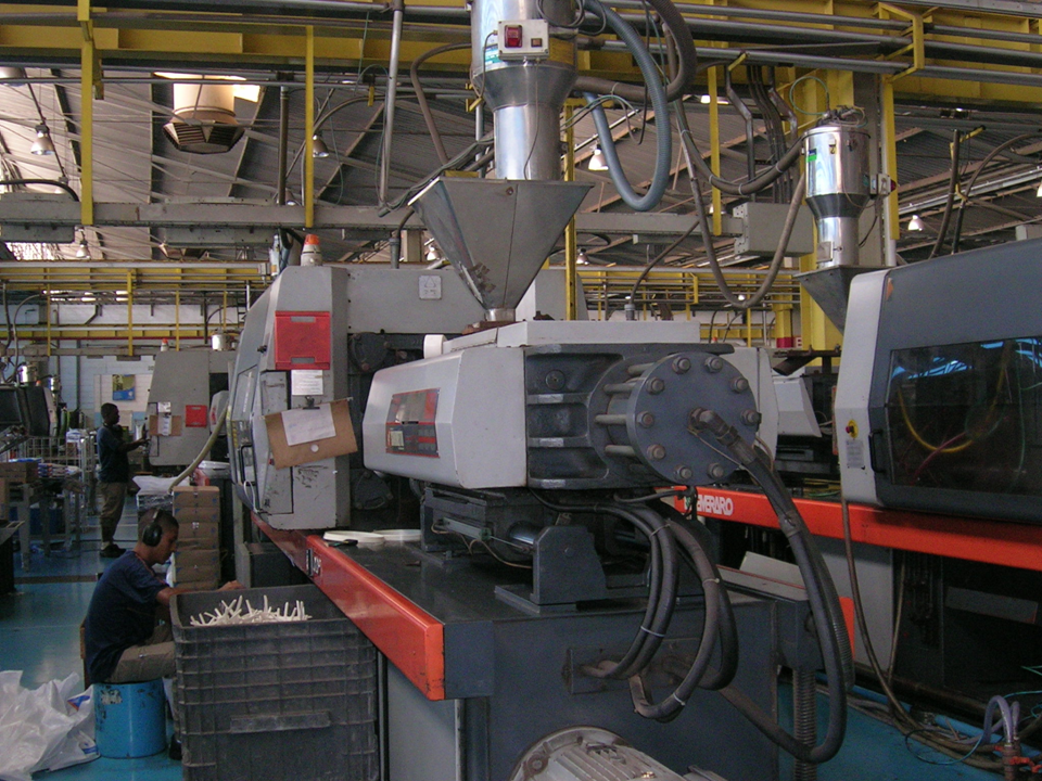
In any standard plastic injection mold, the fundamental split between the moving half (core side) and the fixed half (cavity side) dictates not only the part geometry but also the ejection strategy and cooling efficiency. The fixed half, typically mounted on the injection machine’s platen, houses the sprue bushing, locating ring, and often the main runner system. The moving half, attached to the ejector side, contains the core inserts, ejector pins, and return pins. During clamping, the two halves align via guide pins and bushings—typically with a clearance of 0.02–0.04 mm for standard molds—to ensure precise shutoff. For parts with deep undercuts or internal threads, the moving half may include slide actions or lifters, which are actuated by angled pins or hydraulic cylinders. A common rule of thumb is to place the parting line at the largest cross-section of the part, but this must be balanced against gate location and weld line risk, especially for high-gloss ABS or PC/ABS blends where any mismatch becomes visible.
The molding cycle begins with mold closing, where the fixed and moving halves lock under tonnage—typically 2–3 tons per square inch of projected area for commodity resins like PP or HDPE, and up to 5 tons for stiff materials like glass-filled nylon. Once clamped, molten plastic is injected through the sprue and runner system into the cavity. The melt temperature, injection pressure, and packing time must be tuned to the specific resin; for example, a standard POM (acetal) part might require a melt temperature of 190–210°C, injection pressure of 80–120 MPa, and a packing phase of 2–5 seconds to minimize sink marks. Cooling is the longest phase, often consuming 50–70% of the total cycle time. The mold’s cooling channels—typically 8–10 mm diameter, spaced 2–2.5 times the channel diameter from the cavity surface—must be designed to achieve uniform wall temperature, ideally within ±5°C across the core and cavity. Poor cooling leads to differential shrinkage, warpage, and longer cycle times, which directly hit production cost.
After the part has solidified, the mold opens at the parting line, and the ejector system pushes the part off the core. Ejector pin placement must avoid thin ribs or bosses to prevent stress whitening or pin push marks—common issues in transparent parts. Return pins ensure the ejector plate resets before the next cycle, and in molds with slides, limit switches confirm full retraction to prevent crash. For high-volume production, hardened tool steels like P20 or H13 are standard for cavities, while cores often use S136 or 420SS for corrosion resistance when molding PVC or flame-retardant grades. Venting is another critical detail: shallow vents of 0.02–0.05 mm depth and 6–10 mm width are machined at the parting line to allow trapped air to escape, preventing burn marks. If you are sourcing molds or need reliable tooling suppliers, visit MoldWorld (www.moldw.com) for a directory of vetted mold makers and technical resources.