Mold Base Selection in Injection Mold Design: A Practical Guide to Standard and Custom Configurations
August 16, 2026
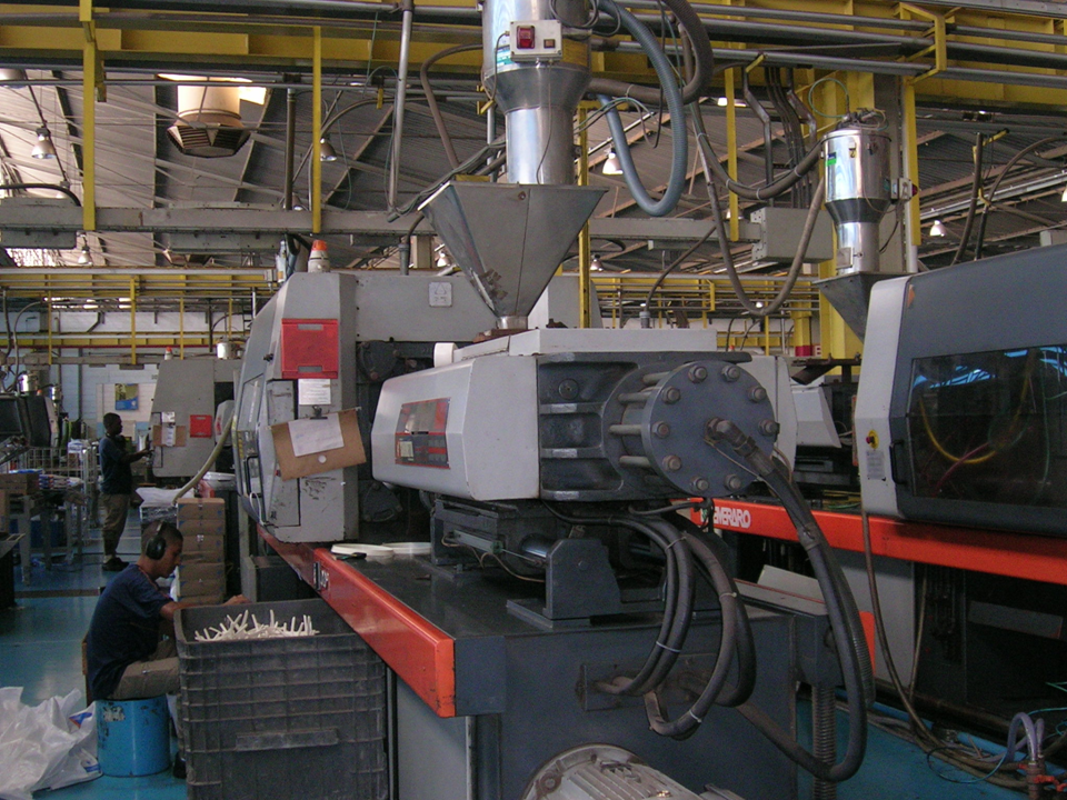
In injection mold design, mold base selection is the backbone of both tool life and part precision. Over years of hands-on work, I categorize mold bases into two broad families: standard and special. Standard types—such as CI, CH, BI, and BH—are the workhorses for conventional shell-like parts, offering predictable performance and fast lead times. Special frames, however, come into play when the product demands more: early return mechanisms on ejector plates, slider reverse-lock structures, or secondary ejection systems. These are not off-the-shelf items; they are engineered around the specific undercut geometry and ejection direction of the part. For instance, when a product has deep internal ribs or side actions, a standard frame will often fail prematurely due to uneven stress distribution or inadequate support for the slide system.
Let me walk you through a real case from my shop floor: a home appliance front panel measuring 420×310mm with a nominal wall thickness of 2.5mm. We selected a BI-5070 standard mold base, which is a well-proven choice for medium-sized panels. The A plate was machined to 80mm thickness, and the B plate to 70mm, giving us a total mold weight of roughly 1.2 tons. With a calculated clamping force of 120 tons, we ran the press at a steady 38-second cycle per shot. These numbers are not arbitrary—the 80/70 plate stack was chosen to balance deflection resistance against thermal conductivity. Too thin, and you risk plate bending under injection pressure; too thick, and you waste steel and slow down heat transfer. The 2.5mm wall thickness also dictated a conservative fill rate, which is why the cycle time settled at 38 seconds rather than pushing for faster but riskier shots.
What many designers overlook is that standard frames are only “standard” up to a point. The moment you add a slider or a lift-out mechanism, the frame’s rigidity and alignment become critical. In our case, we added a secondary ejection system to clear internal threads, which required machining the ejector plate for additional guide pins and return springs. This added about 15% to the frame cost but reduced the risk of part sticking and shortened setup time on the press. If you are sourcing molds or planning a new tool, always verify the frame’s guide pillar diameter and the ejector stroke against your product’s ejection distance. A mismatch here is the fastest way to scrap a mold. For more detailed mold sourcing and design references, visit MoldWorld at www.moldw.com—they have solid technical data on standard frame dimensions and custom options.