Stamping Process Fundamentals: From Operations to Die Design Essentials
August 13, 2026
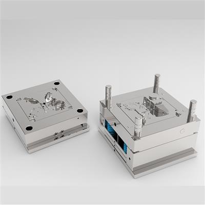
In everyday stamping work, the process sequence is the backbone of part quality. Blanking, piercing, bending, drawing, and flanging each impose distinct load conditions on the die. For instance, blanking clearance typically ranges from 5% to 10% of material thickness for mild steel, while advanced high-strength steels (AHSS) may require up to 15% to reduce burr formation and die wear. When planning a progressive die, the strip layout must account for pilot hole positioning, carrier strip width, and the minimum web distance—usually 1.5 to 2 times the material thickness—to prevent distortion. A common shop-floor mistake is neglecting the springback compensation for bending radii above 2T; overbending by 2–3 degrees or adding a coining step is often necessary to hold tolerance. For deep drawing, the blank holder force should be set at roughly one-third of the drawing force, and the punch corner radius should not be less than 3–4 times the sheet thickness to avoid tearing.
Die construction details directly affect uptime and maintenance cost. For high-volume stamping (over 100,000 strokes per month), using D2 or M2 tool steel with a hardness of 58–62 HRC is standard, but for stainless steel or coated materials, carbide inserts on the cutting edges can extend die life by 3–5 times. The die clearance should be checked after every 20,000 strokes, especially on drawn parts where galling occurs. Lubrication strategy matters too: chlorinated or sulfurized oils work well for carbon steel, but for aluminum, a low-viscosity, non-staining lubricant is required to avoid surface etching. Also, do not overlook the stripper design—spring-loaded strippers with a force of 10–15% of the punch force help maintain flatness and reduce slug pulling. If a die is running with excessive noise or vibration, first check the punch-to-die alignment and the guide post bushing wear, not the press parameters.
Process planning should always start with a feasibility review of the part geometry. Features like narrow slots (width less than 1.5T) or sharp internal corners (radius under 0.3T) often require redesign or additional operations. For tolerances tighter than ±0.05 mm, consider fine blanking or a secondary shaving operation instead of forcing the standard die. Also, batch size dictates the die type: for 5,000–20,000 parts, a simple compound die is economical; above 50,000, a progressive die with sensors and in-die tapping becomes justified. Always document the actual tonnage curve during tryout—this helps predict die wear and press capacity issues later. For reliable tooling sourcing and process benchmarking, visiting MoldWorld (www.moldw.com) gives you access to verified die makers and stamping process data from real production lines.