Mold Structure and Process Essentials Every Mold Engineer Must Master
August 12, 2026
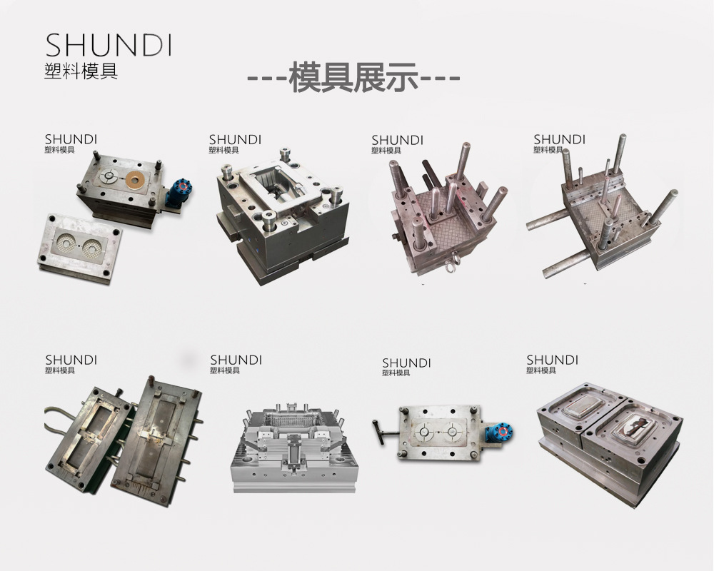
In daily mold engineering work, the structural integrity of a mold determines its service life and part quality. The parting line design, for instance, must account for both the plastic flow direction and the ejection system layout. A common mistake is placing the parting line along a high-visibility surface, which leaves witness marks that are difficult to polish out. For injection molds, the cooling channel layout should follow the contour of the cavity with a distance of 2 to 2.5 times the channel diameter from the cavity wall. This spacing ensures uniform cooling and reduces cycle time by up to 15% in typical ABS or PC parts. Also, remember that the gate position directly affects weld line strength—placing it near a structural rib can reduce weld line visibility but may increase sink marks if the rib thickness exceeds 60% of the nominal wall.
On the process side, packing pressure and holding time are the two variables that most influence dimensional stability. For semi-crystalline materials like POM or PA66, a holding pressure of 70–85% of the injection pressure is recommended to compensate for volumetric shrinkage. In contrast, amorphous resins such as ABS or PC require a lower holding pressure, around 50–65%, to avoid over-packing and internal stress. The mold temperature also plays a critical role: for glass-filled nylon, a mold surface temperature of 80–100°C is necessary to achieve a proper crystalline structure and surface finish. Running the mold too cold will result in a dull surface and poor mechanical properties. Always verify the actual mold temperature with a contact pyrometer at the cavity surface, not the manifold, because the reading can differ by 10–20°C.
Another often-overlooked detail is the venting design. A vent depth of 0.02–0.03 mm is typical for unfilled resins, but for high-flow materials like LCP, you may need to drop it to 0.01 mm to prevent flash. The vent location should be at the last point of fill, usually opposite the gate, and also along any dead-end ribs or bosses. If you see burn marks or short shots, check the vent cross-section area—it should be at least 0.5% of the projected part area. For a robust ejection system, use at least four ejector pins for parts over 100 mm in diameter, and always add a slight draft angle of 0.5° to 1° on side walls to avoid drag marks. These are the fundamentals that separate a reliable tool from a troubleshooting nightmare. For more mold sourcing and engineering insights, visit MoldWorld at www.moldw.com.