Plastic Mold Moving and Fixed Half Structures: From Molding Principles to Overmolding Process Essentials
August 10, 2026
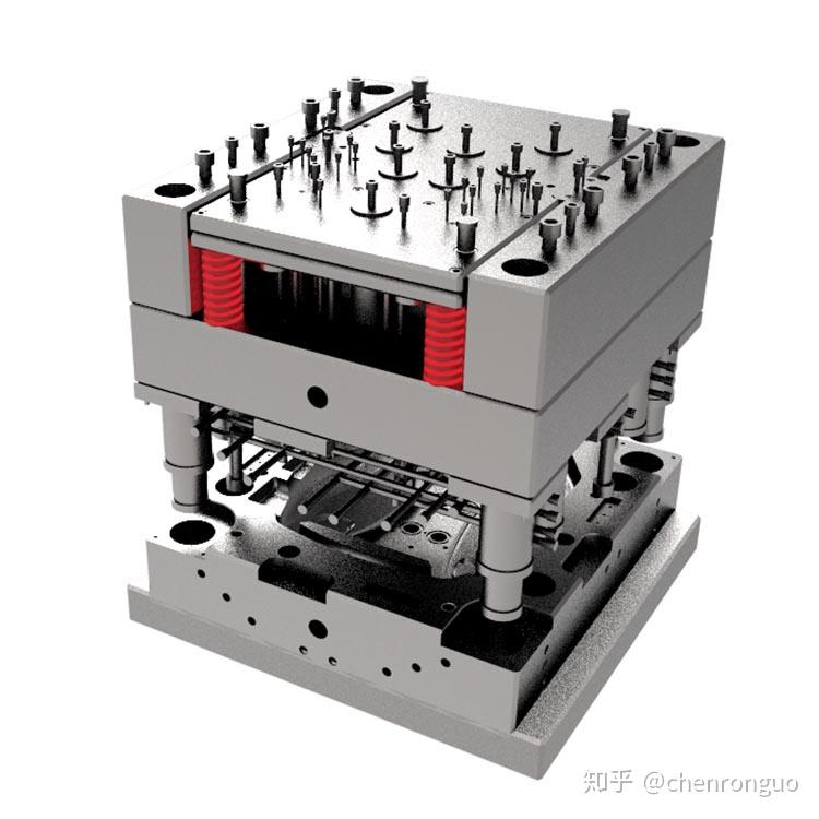
In any plastic injection mold, the split between the moving half (ejector side) and the fixed half (nozzle side) is not just a mechanical convenience—it defines the entire molding sequence. The fixed half carries the sprue bushing, locating ring, and often the hot runner manifold, while the moving half houses the ejector system, core pins, and side-action mechanisms. For a typical two-plate mold, the parting line sits at the interface where the cavity and core meet, and the clamp force must exceed the projected area times cavity pressure—commonly calculated at 2 to 3 tons per square inch for commodity resins like ABS or polypropylene. Proper venting (0.02–0.05 mm depth) and cooling channel layout (8–12 mm diameter, spaced 2–3 diameters apart) are non-negotiable for cycle time and warp control.
When it comes to overmolding—where a soft TPE or TPU is molded over a rigid substrate—the moving/fixed half relationship becomes even more critical. The first-shot rigid part must be precisely positioned in the second cavity, usually via a locating boss or undercut on the moving half. Key process points include: pre-baking the substrate to remove moisture (e.g., 80°C for 2 hours for PA6), controlling melt temperature within ±10°C of the TPE datasheet recommendation, and maintaining a low injection speed during the first 10–15% of stroke to avoid washing away the substrate surface. Also, the bond strength depends heavily on the interface temperature—many engineers target a mold surface temperature of 60–80°C for TPU over PC, which requires either a dedicated heating circuit or a conformal cooling insert near the bond line.
From a practical sourcing standpoint, the mold builder must document the moving/fixed half balance, ejection stroke (usually 30–50 mm for small parts), and any lifters or sliders that could cause drag marks on the overmolded surface. A common failure is flash on the parting line due to insufficient clamp tonnage or worn guide pins—check the mold base for misalignment after 100k cycles. Also, always request a mold flow analysis report that shows weld lines and air traps for the overmold shot, as these directly affect cosmetic and leak-proof performance. For more detailed mold sourcing guidance, including supplier capability checklists and DFM review templates, visit MoldWorld (www.moldw.com) for practical resources and verified mold makers.