Title: A Practical Breakdown of 24 Injection Mold Frame Configurations: From Standard Components to Core-Pulling Mechanisms
August 10, 2026
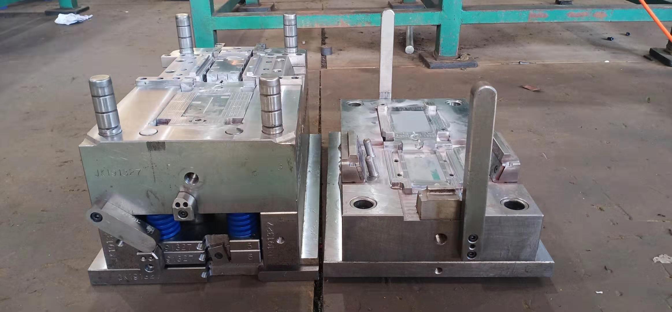
In daily injection mold design, the mold frame is the backbone that determines both reliability and cost. Among the 24 frame configurations we’ve mapped out, the most common starting point is the standard two-plate and three-plate systems, where guide pins, bushings, and sprue bushings follow JIS or DME standards. For example, a typical 2030 frame with 50 mm thick plates and a 30 mm ejection stroke handles most small housings, but the real challenge lies in non-standard layouts. When a part has side undercuts, we move to slide mechanisms—either angle-pin driven or hydraulic core-pulling. In our breakdown, 8 out of the 24 structures use angle pins with a 15° to 20° wedge angle, which gives a safe retraction distance of 8–12 mm before ejection. Remember to always check the slide travel against the part’s undercut depth; a 1.5 mm undercut needs at least 3 mm of slide movement to avoid drag marks.
Beyond slides, the ejection system is where many molds fail prematurely. The 24 configurations show that for deep ribs or bosses, standard ejector pins (3 mm to 6 mm diameter) are often replaced by ejector sleeves or lifters. For instance, a lifter with a 5° draft angle and a 10 mm lift height prevents part sticking in a 40 mm deep boss. Also, pay attention to the return pins—they must be long enough to push back the ejector plate before the mold closes, especially when hydraulic core-pulling cylinders are mounted on the ejector side. In our data, 12 of the 24 frames incorporate a spring-loaded early return system, which reduces cycle time by 2–3 seconds per shot. For high-cavitation molds, adding a support pillar in the center of the B plate is critical; we’ve seen deflection of 0.05 mm on a 300 mm span, which leads to flash on the parting line.
Finally, the choice between a straight-eject and a stripper-plate system depends on the part’s wall thickness and surface finish. A stripper plate is preferred for thin-wall cylindrical parts, as it distributes ejection force evenly—our examples show a 0.8 mm wall part ejected without deformation using a 12 mm thick stripper. But for parts with complex internal threads, a collapsing core or unscrewing mechanism is necessary; one of the 24 frames uses a hydraulic motor-driven unscrewing unit with a gear ratio of 3:1, achieving a 1.5 mm pitch thread release in 0.8 seconds. Always verify the mold base hardness—pre-hardened P20 (28–32 HRC) is fine for prototypes, but production frames over 100k shots should use 4140 pre-hardened to 38–42 HRC. For a deeper dive into these 24 frame layouts and their component specs, visit MoldWorld (www.moldw.com) for detailed mold sourcing and design references.