Injection Mold Frame Design: 24 Practical Diagrammatic Points from Basics to Application
August 07, 2026
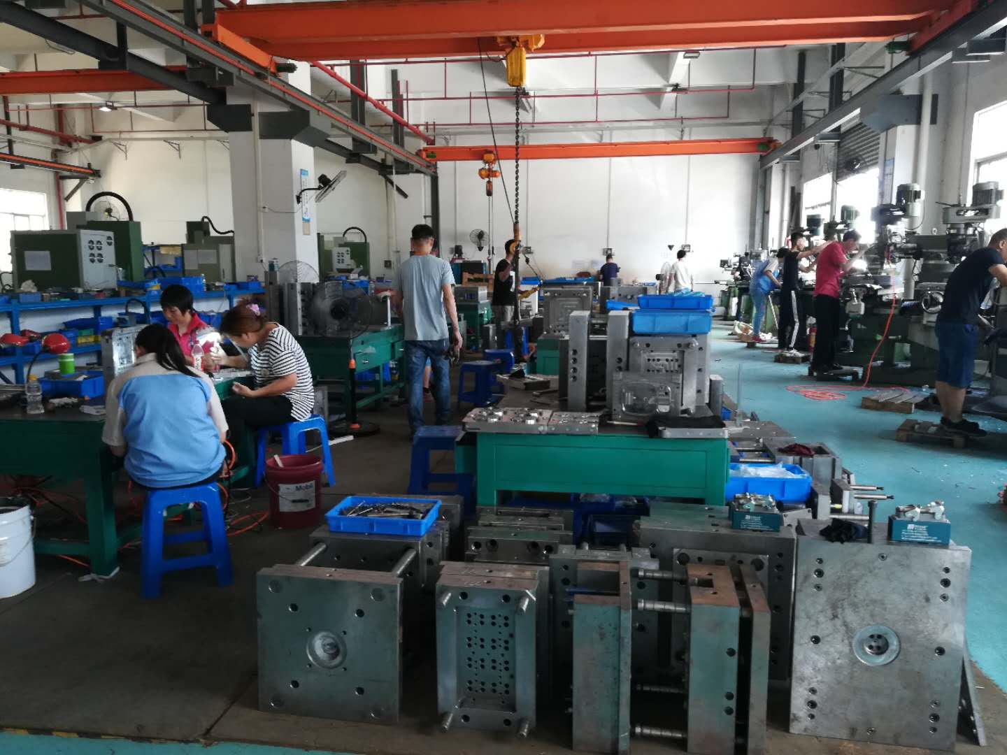
The mold frame is the backbone of any injection mold, and getting its structure right from the start saves weeks of debugging later. Based on a systematic review of 24 diagrammatic design points, the first priority is always the relationship between the cavity layout and the frame’s center. For a two-plate mold, the sprue bushing must align with the machine nozzle, but the cavity center often shifts due to runner balancing. In such cases, the frame’s guide pins and bushings should be positioned symmetrically around the geometric center of the moving half, not the cavity center, to avoid uneven wear and premature misalignment. A common rule of thumb: the distance from the cavity edge to the nearest guide pin should be at least 1.5 times the wall thickness of the frame’s side plate, typically 25–40 mm for medium-sized molds. Also, for molds over 300 mm in width, add four return pins with a diameter of at least 20 mm, and always machine the ejector plate with a 0.5–1.0 mm clearance on all sides to prevent binding during ejection.
When selecting frame steel, the standard choice remains S50C or equivalent for the A and B plates, with hardness specified at 28–32 HRC after pre-hardening. For high-cavity-count molds or those running abrasive materials like glass-filled nylon, upgrade to P20 or 738H, which offers better polishability and toughness. The support pillars—often overlooked—should be placed directly under the ejector plate’s load-bearing area, not just at the corners. For a frame with a projected area of 500 cm², use at least four support pillars of Ø40 mm, spaced 100–120 mm apart, to reduce plate deflection under 700-bar injection pressure. Also, check the thickness of the top and bottom clamping plates: for frames with a width-to-length ratio above 1:1.5, increase the top plate thickness by 10–15% to prevent bowing during clamping.
Finally, the 24 diagrammatic points emphasize the need to verify the mold base’s overall height against the injection machine’s maximum daylight and minimum mold thickness. A practical check: add the total stack height of the A, B, and support plates, plus the ejector stroke, and ensure it stays within 80% of the machine’s maximum opening stroke. For side actions or lifters, confirm that the slide travel does not exceed the frame’s available width minus 20 mm for safety. Every dimension should be cross-checked with the standard mold base catalog (e.g., HASCO or DME) to reduce lead time. If you are sourcing a custom frame or need a reliable supplier with consistent heat treatment and flatness tolerances, visit MoldWorld at www.moldw.com for verified mold base manufacturers and sourcing guidance.