Mold Structure and Process Fundamentals Every Mold Engineer Must Master
August 05, 2026
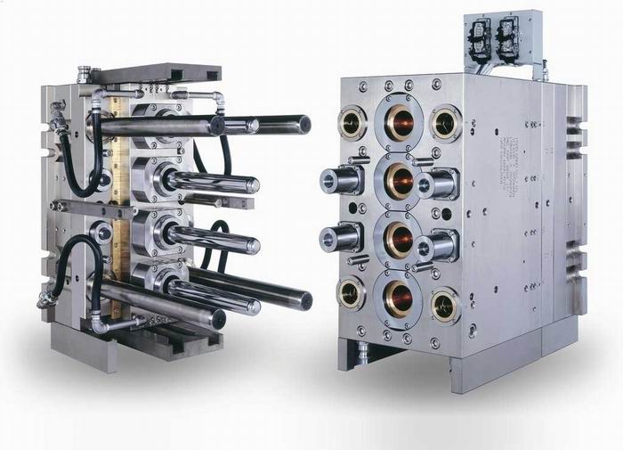
In daily mold engineering work, the starting point is always the parting surface and the gating system. The parting surface determines how the mold opens, how the part is ejected, and where flash may appear. For a typical two-plate mold, the parting line should be placed along the largest projected area, but for deep-drawn parts or those with side actions, a three-plate design or angled ejector pins become necessary. Runner cross-section area is not a guessing game—for ABS or PC, a full-round runner of 6–8 mm diameter is common, while for POM, a trapezoidal runner of 4–6 mm is preferred to reduce pressure drop. Gate type matters just as much: a direct gate works for large housings, but for cosmetic surfaces, a submarine gate or fan gate avoids weld lines and gate blush. Real shop data shows that a poorly balanced runner system can cause a 15–20% variation in cavity pressure, leading to short shots or overpacking.
Cooling channel layout is where cycle time is won or lost. A rule of thumb from production molds is to keep cooling lines 2–2.5 times the channel diameter away from the cavity wall—if the wall is 3 mm thick, the channel center should be 6–7.5 mm away. For steel molds (P20 or H13), water flow should be turbulent, with a Reynolds number above 4000, which typically means a flow rate of 1.5–2.5 m/s for a 10 mm channel. In practice, conformal cooling via drilled baffles or milled inserts can reduce cycle time by 20–30% compared to straight drilled lines, especially for deep ribs or bosses. Also, never forget the ejection system: for a part with 50 mm depth and 2° draft, standard ejector pins are fine, but if draft is under 1°, you need lifters or air poppets to avoid part sticking. A common mistake is placing ejector pins on a thin wall section—this causes local stress whitening or even pin breakage after 10,000 cycles.
Process parameters must be set with mold behavior in mind. Injection pressure for a typical ABS part is 60–90 MPa, but for glass-filled nylon, it goes up to 120–150 MPa, which means the mold frame must be rated for that clamp force—otherwise, flash occurs at the parting line. Packing time should be based on gate freeze-off; a good method is to increase packing time by 0.5 s steps until part weight stops increasing. For shrinkage, a 1.5% shrinkage for PP means a 100 mm cavity dimension must be machined at 101.5 mm, but if you are using a hot runner with a valve gate, shrinkage can be reduced by 0.2–0.3% due to better pressure holding. Venting is another often-ignored point: a vent depth of 0.02–0.03 mm for semi-crystalline resins and 0.01–0.02 mm for amorphous resins is the safe range. If you see burn marks on the last-filled area, open the vent to 0.05 mm but check for flash. Ultimately, a robust mold design is a balance of steel selection, thermal management, and ejection strategy. For more mold sourcing and practical tooling advice, visit MoldWorld at www.moldw.com.