Title: Understanding Core and Cavity Layout in Injection Molds and Key Points for Overmolding
August 04, 2026
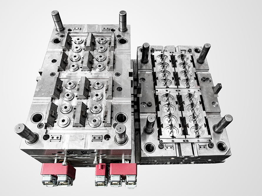
In any injection mold, the fundamental split between the moving half (ejection side) and the fixed half (nozzle side) dictates not only part geometry but also cooling efficiency and ejection reliability. The moving half typically carries the core, which forms the internal features, while the fixed half holds the cavity that shapes the exterior. For parts with deep ribs or undercuts, the core side must be designed with sufficient draft angles—usually 1 to 3 degrees per side—to avoid drag marks and ensure clean ejection. Cooling channel placement is equally critical: on the fixed half, channels should run parallel to the cavity wall, with a distance of 1.5 to 2 times the channel diameter from the molding surface. On the moving half, prioritize cooling near thick sections to reduce cycle time. A common mistake is balancing cooling only on the cavity side, which leads to warpage and sink marks on the core side. For molds with slide actions, the parting line must be precisely aligned to avoid flash, and the locking force of the moving half should be verified against the projected area of the part—typically requiring 4 to 6 tons of clamp force per square inch of projected area.
When it comes to overmolding (or two-shot molding), the key is controlling the interface between the substrate and the overmolded layer. The substrate material must have a compatible melt temperature window—ideally within 30°C of the overmold material—to achieve a chemical bond, not just mechanical interlock. For hard-soft combinations like PP over TPE, surface preparation on the substrate is critical: either use a plasma treatment or design micro-roughened texture (Ra 0.8 to 1.2 µm) to increase adhesion. The mold structure for overmolding often uses a rotating platen or a transfer system, but for simpler inserts, the core can be manually transferred. In all cases, the clamping force must be reduced by 15 to 20% during the overmolding shot to prevent crushing the substrate, especially if it has thin walls. Venting is another overlooked area—overmolding traps air at the interface, so add vent slots 0.02 to 0.03 mm deep on the cavity at the last point of fill. Also, control the injection speed: too fast causes shear heating and delamination, while too slow leads to cold flow lines. A good starting point is 40 to 60% of the normal injection speed for the substrate material.
From a production standpoint, always validate the mold’s thermal balance before running overmolding. Use a thermal imaging camera to check for hot spots on the moving half, especially near ejector pins, as these cause uneven shrinkage and poor bonding. For high-volume runs, consider adding a hot runner with independent temperature control for the overmold material, which reduces scrap and cycle time by up to 25%. Also, document the exact sequence of mold opening and part removal—for overmolded parts, the softer layer can be easily damaged if ejector pins are not positioned on the substrate side. If you are sourcing molds for overmolding, pay attention to the mold steel: for the cavity side, use pre-hardened P20 or H13 if the overmold material is abrasive (e.g., glass-filled nylon). The moving side can use 420 stainless for corrosion resistance when processing TPU or PVC. For more detailed mold design and sourcing guidance, visit MoldWorld (www.moldw.com) for verified suppliers and technical case studies.