Title: Understanding Core and Cavity Dynamics in Plastic Injection Molds: From Molding Basics to Overmolding Precision
August 31, 2026
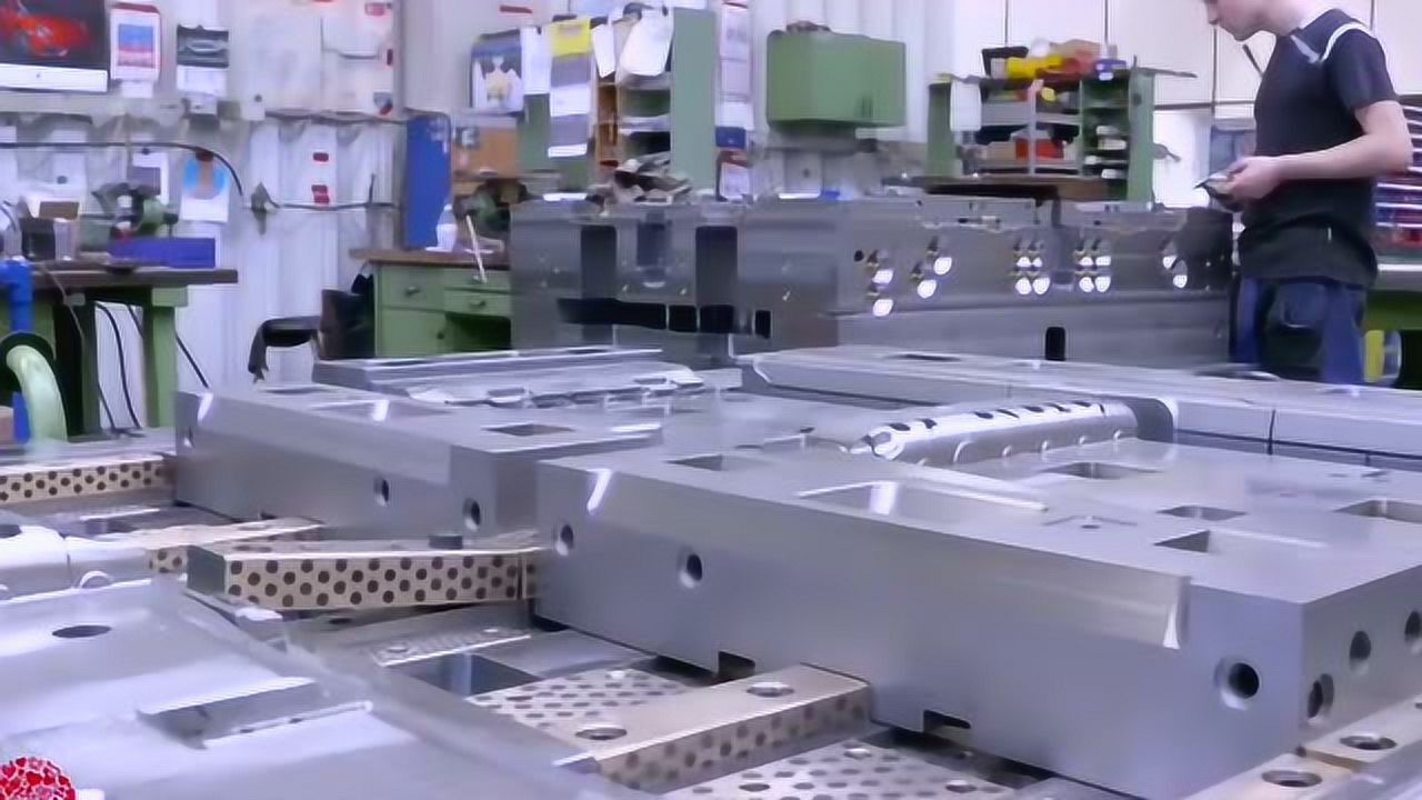
In any plastic injection mold, the split between the moving half (core side) and the fixed half (cavity side) is the backbone of part ejection and dimensional stability. The fixed half, mounted on the injection unit’s platen, carries the sprue bushing and often the hot runner manifold, while the moving half houses the ejector system and slides. For a typical two-plate mold, the parting line must be positioned to minimize undercuts and allow natural draft angles—usually 1 to 3 degrees for most engineering resins like ABS or PC/ABS. A common mistake is placing the parting line across a cosmetic surface, which leaves witness lines that require secondary polishing. In production, the clamping force must exceed the cavity pressure (typically 300–800 bar for unfilled thermoplastics) multiplied by the projected area, otherwise flash appears at the parting line. Real-world molds for automotive bezels, for instance, run at 150–250 tons of clamp for a 200 cm² projected area, with a safety factor of 1.2–1.5.
When it comes to overmolding (two-shot or insert molding), the interaction between the fixed and moving halves becomes more complex. The first shot—usually a rigid substrate like PBT or nylon—is molded in the cavity, then the core rotates or the mold opens to a second cavity where a TPE or TPU layer is injected over it. The key detail is the substrate’s undercut geometry: it must provide mechanical interlocking, not just chemical adhesion. For example, a 0.5 mm deep, 45-degree undercut groove around the perimeter increases peel strength by 40% compared to a flat surface. Also, the moving half must include retractable core pins or angled lifters to release the overmolded part without tearing the soft layer. Temperature control is critical—the fixed half should run 10–15°C cooler than the moving half during the second shot to prevent the TPE from sticking to the cavity. In practice, we set mold surface temperatures via conformal cooling channels, targeting 40–60°C for the TPE side and 80–100°C for the substrate side, depending on the material datasheet.
Another often-overlooked detail is the venting strategy on the moving half. During overmolding, trapped air can cause short shots or burn marks, especially at the end of flow. Standard practice is to cut vent grooves 0.02–0.03 mm deep and 5–8 mm wide on the parting line, but for overmolding, you also need vent pins at the core’s deepest points. I’ve seen molds fail because the vent depth was too shallow for the TPE’s high melt flow index—resulting in incomplete fill at 15% of the cavity. Always verify the material’s recommended vent depth from the supplier. For high-volume runs, add a parting line sensor to detect micro-flash early. If you’re sourcing a mold for a new overmolded product, pay close attention to the mold maker’s experience with rotating cores and hot runner valve gates on the fixed half. For more practical guidance and vetted mold suppliers, visit MoldWorld at www.moldw.com—they list tooling shops that specialize in complex two-shot molds with real production data.